


Thương hiệu - Kính hiển vi
- Cân điện tử
- Máy đo lường các loại
- Máy đo 3 chiều CMM
- Máy đo độ cứng
- Profile projector
- Máy đo độ nhám
- Smart Scope
- Thiết bi đo mới
- Chuẩn Bị Mẫu
- Máy kiểm tra bánh răng
- dau mo cong nghiep
- may cong nghiep
- Air Micrometer
- Máy kiểm tra lò xo, spring testing machine
- ATAGO
- Kanetec
- Vertex
- IMV
- Sotec
- RION
- COSMOS
- LINE SEIKI
- Sekisui
- GRAPHTEC
- HORIBA
- EXTECH
- TAYLOR HOBSON
- THREE-IN-ONE
- DENSO
- TOEI
- KORI SEIKI
- NANOTEC
- WJIT
- RUIBAO
- AMITTARI
- LANDTEK
- OEM
- HUATEC
- ALIYIQI
- LINSHANG
- GIM
- CEM
- DASQUA
- SHUANG LU
- MITSUBOSHI
- ONO SOKKI
- SANHE
- TMK
- AUTONICS
- JAKON
- ZONHOW
- ALEX
- ECHOTECH
- GASTEC
- AIGU
- BOLE
- KSJ
- LEEB
- GIM
- TAKASHIMA KEIKI
- BING M
- MASTECH
- ELITECH
- ANRITSU
- WALTER
- AS ONE
- PCE
- HTI
- RIKEN KEIKI
- RKC
- SMART SENSOR
- MIGISHITA
- SLYB
- KYOTO
- HUATO
- GREENTEST
- Sanko Seikohjyo
- ACCRETECH
- ACO
- HASEGAWA
- Máy hút bụi công nghiệp
- IWASHITA
- FOTEX
- FUTURE TECH
- DAYSENSOR
- PNTOO
- BAILE
- NASEN
- NIHON DENJI
- May do do PH
- Dụng cụ cắt gọt kim loại/ dao kỹ thuật/Cutting tool
- BĂNG TẢI
- Động cơ điện - Motor giảm tốc
- MACHINE TOOLS
- Thiết bị đo PCE-Anh
- Thiet bi do Laserline
- KIMO-Phap
- NIIGATA SEIKI
- BESTOOL-KANON
- HOZAN
- HAKKO
- FUJI TOOL
- SEKONIC CORPORATION
- YAMAMOTO SCIENTIFIC TOOL LABORATORY
- JFE ADVANTEC CO.,LTD.
- CEDAR
- SANKO ELECTRIC
- KETT
- ATAGO
- SUCESS
- OSG
- ISSOKU
- SHIMPO
- SHINKO DENSHI
- A & D
- HIOKI
- SANWA
- DAICHI KEIKI
- NAGANO KEIKI
- KANETEC
- OBISHI
- TECLOCK
- PEACOCK
- CITIZEN
- DIATEST
- MAGNESCALE
- IMADA
- TOHNICHI
- AIKOH
- MITUTOYO
- VESSEL
- ENDO
- URYU
- SIMCO
- OBA
- SATO
- DOM
- OTSUKA
- PEAK
- CARTON
- KANOMAX
- KYORITSU
- EISEN-Pin gauge
- VISION ENGINEERING
- TECPEL
- KURODA
- NPK-Air Tool
- TRIENS
- NICHIDO
- HATAYA
- YODOGAWA-Dust Collection
- MÁY ĐO ĐỘ CỨNG
- NITTO KOHKI
- OJIYAS
- ASAHI
- METROLOGY
- NIKON
- ELECTRONICA
- HEXAGON
- BYC MICROSCOPE
- SOBEK
- CHINO
- YOKOGAWA
- THIẾT BỊ MÀI ĐÁNH BÓNG
- TandD
- THIẾT BỊ TỰ ĐỘNG HOÁ
- SẢN PHẨM KHUYẾN MÃI
- THIẾT BỊ ĐÃ QUA SỬ DỤNG
- ATTONIC
- HIOS
- FLUKE
- OMEGA
- INSIZE
- TOGOSHI
- UNITTA
- RSK
- Renishaw
- KITAGAWA
- KIKUCHI
- ISUZU SEISAKUSHO
- HOKUSO
- KITO-PALANG
- TOYO KOKEN
Danh mục sản phẩm
Dịch vụ sửa chữa
Hỗ trợ trực tuyến
PHONG KINH DOANH
0898980203

HOTLINE3
0909053576
HOTLINE1
0904259271
HOTLINE2
0938825913
Bộ đếm truy cập
 | Đang online | 157 |
| Hôm nay | 501 |
 | Hôm qua | 1330 |
 | Tuần này | 501 |
 | Tháng này | 3224 |
 | Tất cả | 5226254 |
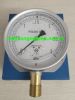
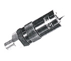
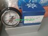
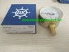
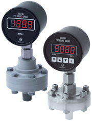
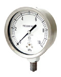
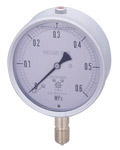
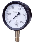
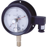
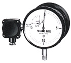
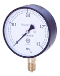
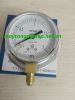
Đồng hồ đo áp suất điện tử Daichi Keiki model DCR, Digital pressure gauge
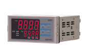
- Tên sản phẩm: Đồng hồ đo áp suất điện tử Daichi Keiki model DCR, Digital pressure gauge
- Model: Đồng hồ đo áp suất điện tử Daichi Keiki model DCR, Digital pressure gauge
- Tiêu chuẩn: JIS
- Xuất xứ: Japan
- Đơn giá: lien he ()
- Bảo hành: 12 Tháng
- Model khác: Đồng hồ đo áp suất điện tử Daichi Keiki model DCR, Digital pressure gauge
Đặt hàng
MÔ TẢ SẢN PHẨM
|
|
|
Model number
![]()
|
Note) digital output: When C5 is added, I cannot use the hold function. |
||||||||||||
|
Multi-input specifications
|
Note 1) Direct current input, the DC voltage input can change the position of scaling and the decimal point. |
||||||||||||||||||||||||||||||||||||||
|
||||||||||||||||||||||||||||||||||||||
Specifications
|
Sản phẩm liên quan
-
 Giá: 3.300.000
 -
 Giá: lien he
 -
 Giá: liên hệ
 -
 Giá: 1.950.000
 -
 Giá: lien he
 -
 Giá: lien he
 -
 Giá: lien he
 -
 Giá: lien he
 -
 Giá: lien he
 -
 Giá: lien he
 -
 Giá: lien he
 -
 Giá: liên hệ
 -
 Giá: lien he
 -
 Giá: 1.950.000
 -
 Giá: lien he